Adding new functionality to a switch controller
Reversing and patching STM32 firmware to add functionality to a third-party Switch controller.
Background
I like RPG games, but with most games I find that there is a bit too much button mashing involved. For example while trying to get through random encounters.

To solve this problem, I added a button mashing feature to a controller, a bit like the turbo buttons third-party SNES controllers used to have. And it’s also something I’ve used often wile playing Pokémon with emulators.
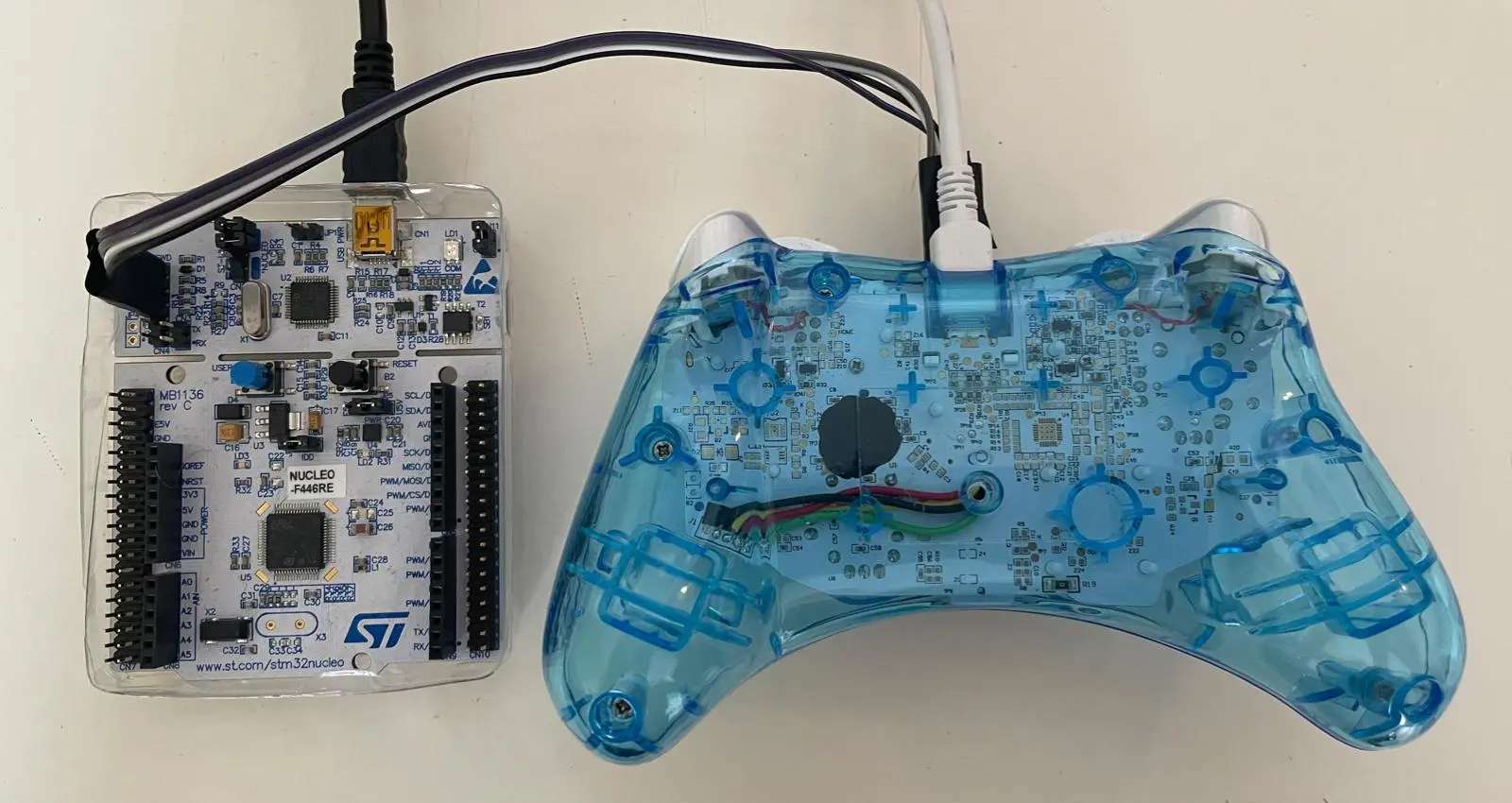
I started this project with a Rock Candy wired Switch controller after coming across a great write-up from Wrongbaud, describing how to interact with a different controller made by the same company using SWD. This is an ARM-specific protocol that (among other things) facilitates JTAG debugging.
Reversing
During a Hackaday talk, Wrongbaud mentioned that his controller also supports USB-DFU. With the Rock Candy controller this is triggered by holding down the + and - buttons while plugging the controller into a computer. This is a nice place to start, since it provides a way to flash and dump the firmware over USB. Later, I tried doing the same or equivalent (start and select) on my other third-party controllers (Hori controllers for the PS4 and Switch), and they also boot into some form of USB update mode… but that’s for another project.
Using what I learned from the write-up, I could also attach a debugger to the controller by soldering some wires to it. Which enabled me to do some fiddling with values in memory. This is a great help in understanding the firmware.

The firmware seems to follow the structure of projects built with STM32CubeIDE, so I could quite easily find the main loop. Then I looked for functions that accessed GPIO pins and set my sights on one that did 18 of them in a row, which was interesting as the controller has 18 digital buttons. By nopping out calls and looking at memory, I could quickly confirm this was the function that read the buttons. Then I could figure out how the button state is stored.

All button states are collected in the r0 register by bit-shifting the button state and storing that value orred with the value of r0 in r0. Let’s look at an example: the encoding of the A button being pressed in binary is 100, and that for B is 10, so when both are pressed at the same time 110 will be stored in r0, whereafter the state collected in r0 will be written to memory.
Getting a foothold
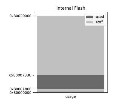
To add functionality, you need to add code to the empty space or somehow make space for it. To identify unused flash, I searched for regions that consist entirely of 0xff bytes, because all the flash bits are set to 1 to when it is erased.

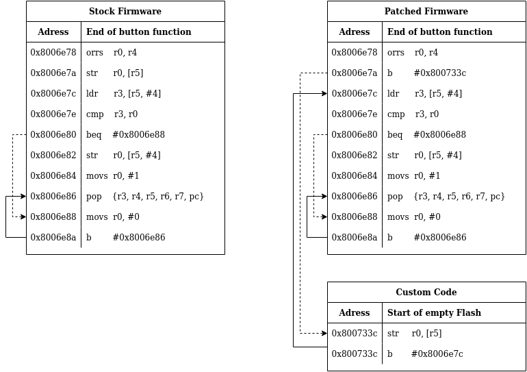
Luckily, less than a quarter of the available flash is used by the stock firmware. Plenty of space to add new features! I started with writing a basic hook. To do this I overwrote an instruction with a branch to empty flash and to the empty flash I wrote the overwritten instruction and a branch back to to the original code.

Patching the firmware
Having a controller that constantly mashes the A button isn’t very usable.
I decided that I wanted to toggle the function by pressing down both analogue sticks at the same time, since this is unlikely to happen on accident, so it won’t mess too much with most games.
When the function is enabled, the A button is pressed on regular intervals without overwriting other button presses. To patch the firmware with some freedom to mess around I wrote a python script. I could not get macro’s to work with keystone so I used python fstrings as marco’s and that worked quite well.
If you take a look at the code, you might have noticed there are some references to LED. The controller has one LED that normally indicates the power state, but it is connected to a GPIO pin, so it’s controllable! To make it more obvious when the custom function is running, it now turns the LED on when pressing a button.
Result
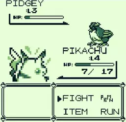
To come full circle, here is a video of the controller beating a pokemon trainer:
I sped up the footage because the battle itself isn’t that interesting.
The Code
#!/usr/bin/python3
from keystone import *

FLASH_FILE = "flash.bin"
PATCH_FILE = "patched_flash.bin"
FLASH_BASE = 0x08000000
LED_CALL   = 0x08006b4C
HOOK_ADR   = 0x08006e7a
RET_ADR    = HOOK_ADR + 0x02
INJECT_ADR = 0x0800733c
DELAY      = 0x20

# Button encoding
BTNS = {'y'    :0x00000001, 'b'    :0x00000002, 'a'     :0x00000004, 'x'    :0x00000008,
        'l'    :0x00000010, 'r'    :0x00000020, 'zl'    :0x00000040, 'zr'   :0x00000080,
        '-'    :0x00000100, '+'    :0x00000200, 'l-stk' :0x00000400, 'r-stk':0x00000800,
        'home' :0x00001000, 'share':0x00002000,
        'right':0x00010000, 'left' :0x00020000, 'down'  :0x00040000, 'up'   :0x00080000}


HOOK_ASM = F"""
.cpu cortex-m0
start:
    b       {INJECT_ADR}
"""

# r0  = button state
# r1  = scratch
# r2  = trigger code (both sticks pressed = 0xc00)
# r3  = led GPIO offset
# r4  = GPIOD
# ...
# r8  = enable state
# r9  = sticks pressed
# r10 = cycle counter

INJECT_ASM = F"""
.cpu cortex-m0
start:
    mov     r7, lr
    push    {{r3,r5}}
    ldr     r2, trigger
    ldr     r3, led
    ldr     r4, gpiod
    cmp     r0, r2
    beq     sticks_pressed
    cmp     r0, #0
    beq     toggle_function
check_enebled:
    cmp     r2, r8
    bne     return
press_button:
    movs    r1, #{DELAY}
    cmp     r10, r1
    blo     dont_press
    str     r3,[r4,#0x18]
    ldr     r1, button
    orrs    r0, r0, r1
    movs    r1, #{DELAY+0x10}
    cmp     r10, r1
    blo     increment
    movs    r1, #0
    mov     r10, r1
dont_press:
    str     r3,[r4,#0x28]
increment:
    movs    r1, #1
    add     r10, r1
return:
    pop     {{r3,r5}}
    mov     lr, r7
    str     r0,[r5,#0x0]
    b       #{RET_ADR}

sticks_pressed:
    mov     r9, r2
    b       check_enebled
toggle_function:
    cmp     r9, r2
    bne     check_enebled
    movs    r1, #0
    mov     r9, r1
    cmp     r2, r8
    beq     disable
enable:
    mov     r8, r2
    b       check_enebled
disable:
    str     r3,[r4,#0x28]
    mov     r8, r1
    b       check_enebled

trigger:
    .long {BTNS['l-stk'] | BTNS['r-stk']}
button:
    .long {BTNS['a']}
gpiod:
    .long 0x48000c00
led:
    .long 0x2000
"""

def assemble(asm, adress=0x08000000):
    try:
        ks = Ks(KS_ARCH_ARM, KS_MODE_THUMB)
        encoding, count = ks.asm(asm.encode(), addr=adress)
        if count == 0:
            print("ERROR: Keystone failed silently")
            exit()
        bytecode = bytes(bytearray(encoding))
    except KsError as e:
        print("ERROR: %s" %e)
        exit()
    return bytecode

def write_to(flash, adress, data):
    flash[adress-FLASH_BASE:adress-FLASH_BASE+len(data)] = data

def main():
    # Assemble needed parts
    nops = assemble("nop \n nop")
    hook = assemble(HOOK_ASM, HOOK_ADR)
    code = assemble(INJECT_ASM, INJECT_ADR)

    # Load flash file
    with open(FLASH_FILE, "rb") as flash_file:
        flash = bytearray(flash_file.read())

    # Apply patches
    write_to(flash, LED_CALL, nops)
    write_to(flash, HOOK_ADR, hook)
    write_to(flash, INJECT_ADR, code)

    # Save patched flash
    with open(PATCH_FILE, "wb") as patch_file:
        patch_file.write(bytes(flash)[:0x10000]) # Only storing 64 kb to save time when flashing
main()